Sunstone Single Pulse research and light production resistance welders are engineered to provide a wide range of welding flexibility. They can provide as little as a few milli-joules of energy for welding microscopic wires and parts, or can deliver up to 100 or 200 Joules for stronger welds. The Sunstone welder is versatile and easy to use. Its interface lets the user quickly select weld settings for a wide variety of welding projects. The welder is designed for use in a research laboratory or light production environment and can be operated up to 166 welds/minute. At Sunstone our goal is to provide quality resistance welding products at affordable prices for small and large businesses.
The Advantages of a CD Spot Welder
Capacitive resistance welders, also called capacitive discharge or CD welders, have many advantages over other welder types:
- Quick energy release for welding highly conductive metals such as copper
- Small heat affected weld zones
- Repeatable energy release independent of line voltage fluctuations
- Capable of extremely fine energy adjustment
CD welders are one of the most cost-effective welding solutions for fine-spot resistance welding. Whether you are manufacturing battery packs or microscopic assemblies, Sunstone CD resistance welders are the most affordable, precision fine-spot resistance welders on the market.
Fundamentals of CD, Fine-Spot Resistance Welding
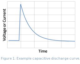 During resistance welding a large electrical current is used to fuse weld metals in one location, or spot, hence the term "spot weld." This weld spot or "nugget" forms during the first few milli-seconds of the welding process. A CD welder performs superior spot welds for several reasons. It allows extremely fast energy release with large peak currents. The discharge speed of a CD welder allows more of the energy to go into weld formation and less into heating the surrounding material. CD welders also keep the heat affected zone - the area where the properties of the metal have been changed - localized to a small area around the weld spot. Fast energy discharge allows electrically and thermally conductive materials, such as copper or aluminum, to be welded. In addition to these features, capacitive welders deliver repeatable welds even during line voltage fluctuations because weld energy is stored before use. Figure 1 shows an example capacitive discharge curve. During resistance welding a large electrical current is used to fuse weld metals in one location, or spot, hence the term "spot weld." This weld spot or "nugget" forms during the first few milli-seconds of the welding process. A CD welder performs superior spot welds for several reasons. It allows extremely fast energy release with large peak currents. The discharge speed of a CD welder allows more of the energy to go into weld formation and less into heating the surrounding material. CD welders also keep the heat affected zone - the area where the properties of the metal have been changed - localized to a small area around the weld spot. Fast energy discharge allows electrically and thermally conductive materials, such as copper or aluminum, to be welded. In addition to these features, capacitive welders deliver repeatable welds even during line voltage fluctuations because weld energy is stored before use. Figure 1 shows an example capacitive discharge curve.
Understanding Weld Resistance
Spot welding relies on metal resistivity (resistance) to heat and fuse metal. During the welding process an electrical current is passed through the weld materials. The metal's resistance causes it to heat and melt. There are two distinct phases in the melting process, namely: heating due to the weld materials' contact resistance and heating due to bulk material resistance.
Figure 2 shows an example of a micro-scale surface profile. On the micro-scale, surfaces are rough and mating surfaces only contact in a limited number of locations. Because the surfaces have limited contact area, this area has a higher electrical resistance than the metals' bulk resistance. The resistance is called contact resistance. In fine-spot welding applications contact resistance is the most important factor in weld formation. During the first few milli-seconds of weld formation the high-resistance metal bridges melt allowing other bridges to come into contact to continue the melting process. When all of the bridges have fused, the contact resistance is zero. The bulk resistance of the metal then completes the weld.

Weld Pressure
One way contact resistance can be controlled is through the pressure of the welding electrodes. High electrode pressure reduces contact resistance because the pressure creates more metal bridges or contact points (Figure 2). When contact resistance is reduced, less weld power is consumed at the material interface and therefore the weld is cooler. Conversely, less weld pressure translates to higher contact resistance and a hotter weld. Electrode pressure also contributes to weld strength. The applied pressure forces the liquid metal together during the welding process and allows the metal to mix and solidify. An appropriate amount of pressure should be used to ensure proper weld nugget formation. Table 1 demonstrates how electrode pressure affects weld formation.
| Pressure |
Weld Heat |
Weld Strength |
| Up |
 |
 |
| Down |
|
|
Table 1: Weld properties with electrode pressure. Weld nugget strength is related to weld mixing.
Electrode Configurations
Figure 3 shows several electrode configurations used in resistance welding. Figure 3a. is called a direct or opposed weld. During welding current passes from one electrode, through both work pieces, and out an opposing electrode. Figure 3b. shows a step electrode configuration. This configuration is used when there is access to only one side of the work piece and an electrode can be placed on both materials. Figure 3c. is a series or parallel configuration. It is used when electrodes can only be placed on one metal surface from one side. This weld configuration requires more weld energy because the current is divided between the two work pieces.

CD Weld Energy
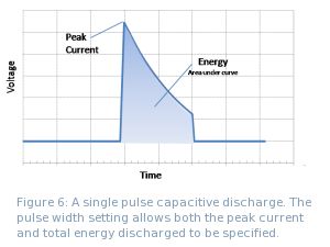
A capacitive discharge welder controls the voltage of the welding capacitors. However, the energy stored in the capacitor is a function of the voltage squared (See Eqn. 1). A small difference in weld voltage makes a large difference in weld energy. Peak weld currents and voltages occur at the beginning of the weld cycle and then drop off exponentially (see Figure 1).

Using Sunstone Single Pulse Spot Welders
Weld Energy Indication
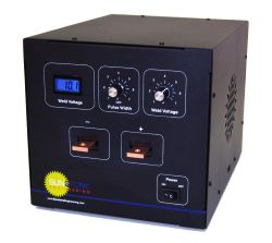
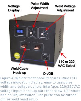
Figure 4 shows the Sunstone Single Pulse CD welder front panel. The LCD display indicates weld voltage. To convert weld voltage to watts*seconds (Joules) use Eqn. 1 or see Table 2 for a simplified list.
Energy Adjustment and Pulse Control
Sunstone Single Pulse welders allow a large degree of control over the entire welding process. The energy stored and released with each weld discharge can be infinitely adjusted between minimum and maximum values. The pulse width dial allows fine control over the duration of the weld pulse and the energy released with each pulse. The weld voltage knob controls the total welder energy storage (see Table 2 and Eqn. 1) and also sets the peak weld current. Peak current can be calculated from the weld voltage divided by the total system resistance. Typical values of peak current with weld voltage and load are given in Table 4. The amount of energy released for each pulse width setting is shown in Table 3 and is a function of the welding load (resistance).
Sunstone Single Pulse welders have weld repetition rates of up to 166 welds/min (the hardware defined limit) by using an external power supply booster. Without the power supply booster the user can expect repetition rates (to maximum energy) of 30 welds/min and 13 welds/min for the CD100SP and CD200SP, respectively. Table 5 gives additional details of repetition rates with weld voltage.
How to Use the Pulse Width Dial
 Controlling voltage (energy storage) and pulse width allows the user to manage both the energy released during the welding process and the peak electrical current experienced by the weld material. These parameters are important when welding materials that have diverse thermal and electrical properties. Controlling voltage (energy storage) and pulse width allows the user to manage both the energy released during the welding process and the peak electrical current experienced by the weld material. These parameters are important when welding materials that have diverse thermal and electrical properties.
There are several factors that should be considered when selecting the correct pulse width setting. For example, when welding highly conductive materials such as copper, the peak weld current must be higher than resistive materials (e.g. steel). Thus welding a thin copper part may require a high weld voltage (peak current) but a small pulse width (total energy). Conversely a thin steel part may require a lower weld voltage (peak current) and longer pulse width (to provide enough energy). Figure 6 shows how voltage, peak current and energy relate.
Weld Actuation
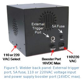
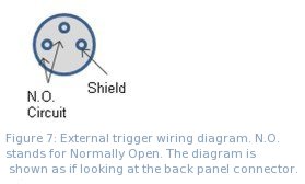
The welders are actuated by means of an external trigger port located on the back of the welder (see Figure 5). The trigger uses a DIN 3 connector and requires shielded wire. Figure 7 shows the proper pin placement for custom external trigger cables. The diagram is shown as if looking at the back panel. The standard external trigger cable connector is an SD-30LP made by CUI Inc.
 Weld Attachments Weld Attachments
Sunstone Engineering offers a variety of welding hand pieces and weld heads to accommodate a diverse range of welding applications. Hand piece welding attachments allow flexibility in electrode placement, while fixed weld heads provide control and precision. Table 3 indicates the pulse settings to be used with different cabling (load). Table 4 indicates peak currents that can be expected with cable sections totaling 6 feet. Typically, hand pieces will use 4 or 8 AWG gauge wire while weld heads will be connected with 1 or 4 AWG gauge wire. The copper connection bars accept 1/4" (6mm) studs.
Determining Weld Performance
Typically, a weld pull test should be done to determine the correct weld settings for a new welding process. During the test, welds are pulled until breakage with specific force or performance criteria in mind. For example, a nickel strip to nickel plated steel weld, typically seen in battery pack manufacturing, should pull apart leaving holes in the thin nickel metal and weld nuggets on the battery terminal.
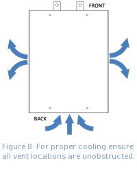
Welder Cooling Considerations
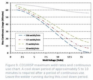
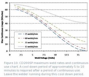
Proper ventilation is required when using Sunstone Single Pulse welders, as shown by Figure 8. Figures 9 and 10 show the maximum repetition rates and continuous use times for the CD100SP and CD200SP welders (respectively). Cool down periods after maximum use times should be between 5 and 10 minutes. Leave the welder running during this cool down period.
Voltage and Power Requirements
Sunstone Single Pulse welders can be configured by the user to accept 110 or 220VAC wall power. Please select the appropriate setting (110 or 220 VAC) on the side of the welder as indicated in Figure 4. The welder uses a 5mm x 20mm 5A fuse. A 300W wall circuit should be used to run the welder.
Tables
Quick-reference Tables 2 – 7 provide useful information for using Sunstone Single Pulse welders.
SAFETY
All welds are performed at low voltage for increased safety of operation. Please follow these points to help ensure your comfort and safety.
- Always wear safety glasses when working with spot welders and weld heads.
- Remove hand jewelry before welding.
- Avoid touching weld spots immediately after the weld has been performed as they will be hot.
- Be careful not to pinch fingers in moving weld head parts or between welding electrodes.
Table 2: Energy storage in watts*seconds (Joules) as a function of weld voltage.
| Model |
Voltage (volts) |
| 0.2 |
1 |
2 |
3 |
4 |
5 |
6 |
7 |
8 |
9 |
10 |
11 |
12 |
13 |
14 |
15 |
16 |
16.5 |
| CD100SP |
0.015 |
0.4 |
1.6 |
3.6 |
6.4 |
10 |
14.4 |
19.6 |
25.6 |
32.4 |
40 |
48.4 |
57.6 |
67.6 |
78.4 |
90 |
102 |
109 |
| CD200SP |
0.032 |
0.8 |
3.2 |
7.2 |
12.8 |
20 |
28.8 |
39.2 |
51.2 |
64.8 |
80 |
96.8 |
115 |
135 |
157 |
180 |
205 |
218 |
Table 3: Percent energy release as a function of weld cable gauge number (AWG) and Pulse dial setting. Four and eight AWG cabling are typically seen when using hand held attachments.
| |
CD100SP |
CD200SP |
| Pulse Width Dial Marker |
Pulse Time (ms) |
1 AWG
(% discharge of stored energy) |
4 AWG
(% discharge of stored energy) |
8 AWG
(% discharge of stored energy) |
Pulse Time (ms) |
1 AWG
(% discharge of stored energy) |
4 AWG
(% discharge of stored energy) |
8 AWG
(% discharge of stored energy) |
| 1 |
0.26 |
27% |
20% |
12% |
0.47 |
25% |
19% |
10% |
| 1.5 |
0.28 |
29% |
22% |
12% |
0.50 |
26% |
20% |
11% |
| 2 |
0.45 |
42% |
33% |
19% |
0.81 |
39% |
30% |
17% |
| 2.5 |
0.59 |
51% |
40% |
24% |
1.07 |
48% |
37% |
22% |
| 3 |
0.75 |
60% |
48% |
29% |
1.34 |
56% |
44% |
27% |
| 3.5 |
0.90 |
67% |
55% |
35% |
1.63 |
63% |
51% |
32% |
| 4 |
1.06 |
72% |
60% |
39% |
1.90 |
69% |
56% |
36% |
| 4.5 |
1.43 |
82% |
71% |
49% |
2.57 |
79% |
67% |
45% |
| 5 |
2.23 |
93% |
86% |
65% |
4.02 |
91% |
83% |
61% |
| 5.5 |
3.54 |
99% |
95% |
81% |
6.37 |
98% |
94% |
78% |
| 6 |
4.80 |
100% |
98% |
89% |
8.65 |
99% |
98% |
87% |
| 6.5 |
5.51 |
100% |
99% |
92% |
9.92 |
100% |
99% |
90% |
| 7 |
5.54 |
100% |
99% |
93% |
9.98 |
100% |
99% |
90% |
Table 4: Peak weld current as a function of weld voltage and external cabling AWG gauge number (assumes 6 total feet of cabling). Four and eight AWG cabling are typically seen when using hand held attachments.
| Voltage |
1 AWG
0.8mOhm Load
(Amps) |
4 AWG
1.6mOhm Load
(Amps) |
8 AWG
4.0mOhm Load
(Amps) |
Voltage
(continued) |
1 AWG
0.8mOhm Load
(Amps) |
4 AWG
1.6mOhm Load
(Amps) |
8 AWG
4.0mOhm Load
(Amps) |
| 0.2 |
98 |
70 |
38 |
10 |
4878 |
3509 |
1805 |
| 1 |
488 |
351 |
190 |
15 |
7317 |
5263 |
2857 |
| 5 |
2439 |
1754 |
952 |
16.5 |
8049 |
5789 |
3143 |
Table 5: Weld speed in welds per minute at 100% energy discharge. Nominal repetition rate and increased repetition rate with PS25A power supply (PS) booster are given.
Energy set-point
(% of maximum energy) |
NOMINAL
Rep Rate
CD100SP
(welds/min) |
NOMINAL
Rep Rate
CD200SP
(welds/min) |
PS BOOSTER
Rep Rate
CD100SP
(welds/min) |
PS BOOSTER
Rep Rate
CD200SP
(welds/min) |
| 100% |
29 (100 ws) |
13 (200 ws) |
*166 (100 ws) |
*72 (200 ws) |
| 75% |
33 (75 ws) |
15 (150 ws) |
*166 (75 ws) |
*98 (150 ws) |
| 50% |
41 (50 ws) |
21 (100 ws) |
*166 (50 ws) |
*166 (100 ws) |
| 25% |
45 (25 ws) |
23 (50 ws) |
*166 (25 ws) |
*166 (50 ws) |
| MIN |
9 (0.015 ws) |
7 (0.3 ws) |
NA w/PS25A |
NA w/PS25A |
| *See figures 9 and 10 for maximum continuous-use and cool-down periods. |
Table 6: Weld pulse characteristics.
| Model |
Min and Max Energy Set-Point |
Pulse Width |
Rise Time
(to max. voltage) |
Min. Pulse Height |
| CD100SP |
0.015 ws - 100 ws |
Min |
0.26 ms |
0.15 ms |
0.2 V |
| Max |
5 ms |
| CD200SP |
0.03 ws - 200 ws |
Min |
0.47 ms |
0.15 ms |
0.2 V |
| Max |
10 ms |
Table 7: Sunstone Single Pulse welder physical characteristics.
| |
CD100SP |
CD200SP |
| Inches |
cm |
Inches |
cm |
| Height |
8 |
20.3 |
8 |
20.3 |
| Width |
8.5 |
21.6 |
8.5 |
21.6 |
| Depth |
11 |
28 |
11 |
28 |
| Weight |
17 lbs (8 kg) |
19 lbs (9 kg) |
|